Copyright (©) Harald Milz 2001
Put under the GNU General Public License (GPL)
See www.gnu.org.
This project starts to become more and more concrete. If I haven't made any drastic thinking errors the basic concept should be all right, and there is nothing in it which makes it physically or economically impossible. I am still looking for serious fellow developers... :-)
Damn - the beast starts needing a name.
Commercial disclaimer: I have no commercial interest in this project, and do not plan to market it. I would gladfully cooperate with any capable firm to produce this unit, though, be it a small startup or be it Roland if they ask me kindly :-) Before you start to produce and market these things be sure to read the GNU General Public License, though. It requires you to put all derived work under the GPL as well.
The 6 GK pickup signals are ADC converted using low-power audio ADCs, as well as the normal guitar signal and a duty cycle modulated Synth Volume voltage. The 4 resulting stereo signals as well as S1 and S2 are then converted to ADAT using an Alesis Semiconductor AL1401A ADAT optical protocol generator (OptoGen).
The receiver decodes the ADAT data stream using a Alesis Semiconductor AL1402 ADAT optical protocol decoder (OptoRec) and fed into 4 stereo DACs (CS4335, 24-bit left justified) or a 8-channel DAC (CS4382). Synth Vol is restored, as are S1 and S2.
Both conversion stages will take place at 24 bit / 48 kHz which is what both the ADAT chips and the low-power ADCs provide.
The DIY project stops at the video signal output and input, respectively. The DIY'er has to provide his or her own video transmitter link i.a.w. national regulations, as well as the power source.
Expected performance:
The video link will perform best in an environment without much noise (what else is new?). Everyone transmits on 2.4 GHz now. Diversity receiver preferred, possibly in the 5.8 GHz ISM band. Extremely expensive, it seems.
This is just a broad concept. Feel free to comment, rip apart, rewrite, make up new ideas, etc.
This method results in a net sample rate of 16 kHz per channel. The guitar signals are well below 8 kHz. The 0.01dB passband edge is 0.4535*Fs = 21.7 kHz - we need to add low passes to the ADC inputs.
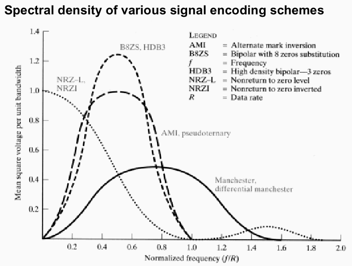
The Biphase-Mark signal for a 24/48 stereo ADC channel has 48,000 samples/s * 64 Bits/sample = 3.072 Mbps; a SPDIF subframe has 32 bits per sample. It uses a bandwidth of about 3.072 * 1.6 = 4.92 MHz (see chart) and thus fits nicely in a 5 MHz video channel. The Biphase-Mark signal and its variant, the Manchester code, are discussed here. I have one witness saying SPDIF runs fine over the cheap X-10 video transceivers. See also the thread in de.sci.electronics. Sorry, this thread is in German but you can always use the Babelfish translator to get funny results.
For a discussion of spectral densities of the modulations methods see also
Downside: we can't transmit guitar and all 6 GK signals at the same time (except if I use 4 stereo ADCs and reduce the sample rate to 12 kHz per channel instead of 16). We can select GK only, guitar instead of E1, guitar instead of E6, though. But I want to find a way of omitting S1 (see Tx block diagram) - I want to use the selector switch on the GK controller. A full wave rectifier and comparator could do that.
Running the SPDIF transmitter in professional mode yields the following user bits we can transmit:
| 8402A pin | 8412 pin | user data |
|---|---|---|
| V | VERF | Synth Vol PCM 1 |
| U | U | high during ADC3 active |
| C | C | must not be used and tied low. |
| EM0 | Cb = EM0 | S1 |
| EM1 | Cc = EM1 | S2 |
| /C1 | Ca = /C1 | PM0 |
| /C9 | Cd = /C9 | PM1 |
| -- | Ce = /CRCE | CRC error -> LED warning |
where the Pickup Mode PM is as follows (example):
| S1 | PM0 | PM1 | GK Pickups | Guitar |
|---|---|---|---|---|
| Mid | 0 | 0 | GK1-6 | -- |
| Down | 0 | 1 | GK1-5 | Guitar |
| Up | 1 | 0 | GK2-6 | Guitar |
The required level shift between the 3.6 and 5V parts in the transmitter is achieved by the 74HC4050 for SCLK, LRCK, /RST, and MCLK.
The rest of the circuit is pretty straightforward. The multiplexer 74HC153 selects the ADC whose corresponding 4017 counter pin is on "1". The counter is reset when the counter reaches 3. It is clocked by the rising edge of LRCK.
The "U" bit indicating ADC1 is triggered when ADC3 is active. It is sampled with the MSB, and "transmitted with the audio sample entered before the FSYNC edge that sampled it." (CS8401/02A data sheet, pg. 20). In the receiver, it will thus be output when the ADC1 sample is shifted out of the CS8412.
The Reset circuit resets the CS8402A on power-on, and the ADCs a fraction of a second longer, until the clocks are stable.
The standard resistor divider for the consumer type output creates a voltage of 0.5Vss. We should drive the video transmitter full scale, though (1Vss), i.e. we need to replace the resistor with 187.5 and 125 Ohm 1% resistors. 180/120 is fine with a slight imbalance (72 Ohms). 187/124 are standard E96 values.
The analog cicuitry on the left is powered with ±5V, the ADCs and the 74HCs in the middle including the 74HC4050 level shifter with 3.6V, and the CS8402A with +5V. The CS8402A has TTL compatible inputs and thus accepts the 3.6V HCMOS outputs. The ADCs' VL and VA pins are decoupled with a ferrite bead (see application notes).
We need about 10mA for ±5V, 35 mA for 3.6V, and 20mA for 5V.
Update: The GK-2A controller uses +7V to generate the 5V for synth vol using a resistor in series with the pot. No problem if we multiply the synth vol voltage by 7/5 at some stage. Everything else in the GK-2A will do fine with +5V.
Most components should be SMD. Everything should fit on a 80x100mm PCB (half Euro card, that's what the freeware Eagle layouter can provide) - a stacked 80x70mm daughter card may be needed. Since the 13-pin PCB connector is 22 mm high including leads the case should be 24-25 mm high internally at least anyway. An alternative would be to use no 13-pin PCB connector (who makes the 30cm 13-pin stub cable?) but permanently attach the cable to the PCB. The PCB needs to provide a 14-pin in-line plug too.
Using SMD components is a challenge for soldering... The CS5333's pin pitch is 0.65mm max. ...
If you prefer to stick the battery case in your trouser pocket you can use a smaller case without batt compartment (sounds like 110x90x30 mm). In this case a lockable power connector is a must!
Upper PCB, all analog circuitry:
Lower PCB, all digital stuff:
Another possibility is using the Graham Patten ADAT-1 and ADAT-2 analog-to-ADAT converters.
By the way the ADAT patent US5297181 is here (well, sort of).
But read on if you like...
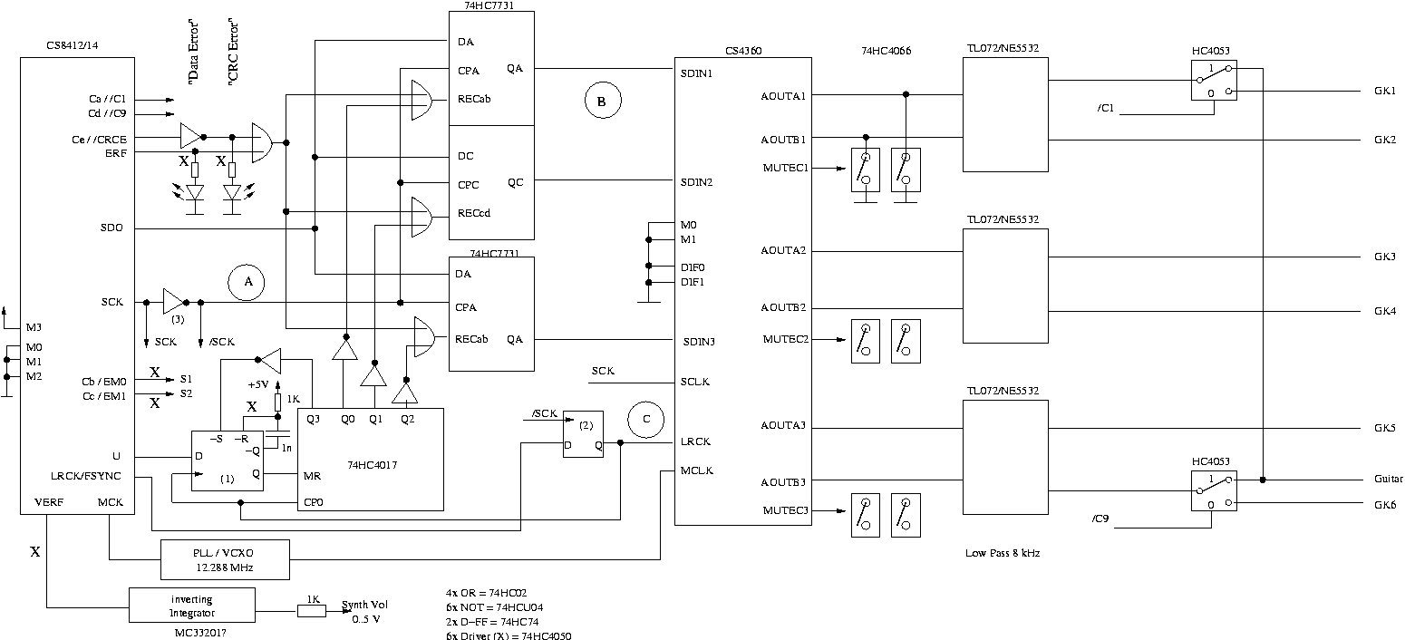
The demultiplexer in the receiver is a 4017 type counter triggered by the rising edge of LRCK (delayed by half a SCLK, see below), 3 64 bit shift registers (2x 74HC7713), plus some OR gates.
If data is shifted out of SDO by the CS8412, it is clocked into the shift register whose corresponding counter output is on "1", except if there is an error (ERF or /CRCE). In case of an error, or if the corresponding counter pin is on "0", the shift register is switched to "recycle", i.e. the frame is repeated one more time. No interpolation - that would require a DSP.
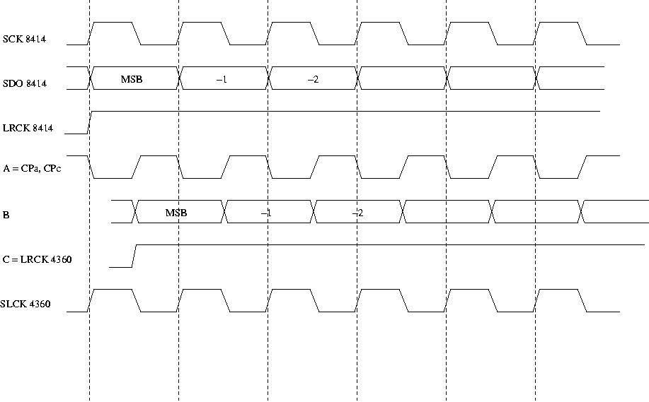
Since the shift register latches the audio data on the falling (inverted) edge of SCK, it effectively delays the data by half a TSCLK. To maintain the correct timing for the DAC, we need to latch LRCK at the falling edge of SCK (thus delaying it by half a SCK as well), and keep SCK for the CS4360. This is achieved by D flipflop (2) and the clock phase inverter (3). Timing see diagram - it shows how everything is delayed by one half of TSCLK.
The 4017 counter is reset on the rising edge of LRCK if "U" is high, or if the count reaches 3. The reset mechanism seems a little weird but I had a spare flip-flop (1)... If Q3 goes high, /S of the FF is pulled low, and the FF's Q goes high which resets the counter. /Q of the FF goes low, and the RC highpass issues a 1µs impulse which resets the FF. The 4050 buffer just protects the FF's input from the high spike when /Q goes up again.
We'll take ±7V for some OPs from a connected GK device.
Or does someone have a working application for the Analog Devices AD6600?
http://www.dynapix.com/supertriad.htm ?
A very interesting system is S-515P on http://www.cocom.com/acatalog/Online_Catalog_CVT_500_29.html. A bit expensive for hobbyists maybe.
Over time, we will try to compile a list of appropriate video transmitters.
- Conrad pp. 519/882.
- the Gigalink module offers 5 selectable channels.
-> use alarm switch connector for S1/S2 ?
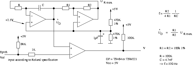
-> use microphone input for synth vol VCO signal
-> hence only 7 audio channels over video FM.
ELV (www.elv.de): 4-Kanal-Sendesystem ALM 2442 399 DM (set!)
- transmitter uses 4.8..7.2V, i.e. Vbat directly.
- has audio channel (reset)
- can use a case w/ 4 AA-cell battery compartment.
- batt cptmt: Conrad 521868 or external battery
pack w/ cable
- also nice: Bopla BOS 752 or 807
(http://www.bopla.de/, w/ 4 AA-cell
battery compartment) (Reichelt pg 179/80)
https://spynet.xynx.com:
- auch 25 mW Minisender. (auch Gigalink - 2004311, 390 DM)
- angeblich nur 120 mA
- Mini TX II 10 oder 25 mW (?) 2200012 480 DM
- Empfänger 2048020 229 DM (COnrad 329 DM)
-> non-diversity :-(
http://www.securitec-gerlach.de/: very
cheap. Quality?
http://www.dynapix.com/oem.htm ? Only signel
frequency, needs 500 mA!
Diversity:
http://www.premierewirelessinc.com 5.8 GHz
I have got one hint saying the cheap X10 transceivers
work fine for SPDIF
(http://www.x10.com/products/offer105.htm)
Ultra small, nice but expensive:
http://rf-links.com/24_transmitters.htm